Introduction
Custom power supply cables give PC builders control over both aesthetics and exact electrical specifications. Most builders underestimate what's involved — proper wire gauge selection, connector compatibility, crimp quality, and PSU pinout knowledge all determine whether the result is clean and safe or a fire risk waiting to happen.
Get any of those variables wrong, and you're looking at damaged components or worse.
This guide covers what materials and tools are needed, the exact steps to build cables from scratch, the variables that determine quality, and the most common mistakes to avoid.
Key Takeaways
- Build custom PSU cables by selecting the right wire gauge, crimping compatible connectors, and testing continuity before installation
- Always verify your PSU's pinout before building — incorrect wiring can permanently damage your GPU, motherboard, or PSU
- Core tools needed: wire stripper, crimping tool, multimeter, and connector pins rated for your PSU's connector type
- Test with a multimeter before plugging in — it confirms correct continuity and rules out shorts
- Worth making when standard kits don't offer the length, look, or configuration your build requires
What You Need to Make Custom Power Supply Cables
The right materials and tools determine whether the finished cable is safe and functional. Using the wrong gauge wire or incompatible connectors is a leading cause of shorts, overheating, and connector failure.
Tools Required
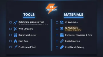
Essential tools for safe cable building:
- Ratcheting crimping tool — Must match your connector pin type. The ENGINEER PA-09 (for 1.0-1.9mm dies) and PA-20 (for 1.6-2.3mm dies) are recommended for Molex Mini-Fit Jr. terminals used in ATX, EPS, and PCIe cables
- Wire strippers — Precision adjustable strippers rated for 18-24 AWG to cleanly cut insulation without nicking conductor strands
- Digital multimeter — For continuity testing and voltage verification before installation
- Heat shrink tubing gun or lighter — To secure sleeving at connector ends
- Pin removal/insertion tool — Molex extraction tool (part number 11-03-0044) for ATX, EPS, and PCIe connectors
Materials Required
Core materials for cable construction:
Wire:
- 18 AWG stranded copper wire for ATX 24-pin, EPS 8-pin, legacy PCIe 8-pin, and SATA connectors
- 16 AWG stranded copper wire for modern 12V-2x6 (600W) GPU connectors — the PCI-SIG CEM 5.1 specification mandates this to handle 9.2A per pin
Connectors:
- PSU connector housings and pins matched to your specific PSU model
- ATX 24-pin, EPS 8-pin, PCIe 6+2-pin, or SATA connectors
- Molex Mini-Fit Jr. 5556 series terminals for standard applications
- Molex Mini-Fit Plus HCS 45750 series terminals for high-current applications (rated up to 11A on 18 AWG wire)
Optional:
- Cable sleeving (nylon, PET, or paracord)
- Heat shrink tubing
- Cable combs for aesthetics
Source wire and connectors from established electronics distributors like Digi-Key, Mouser, or dedicated PC sleeving suppliers. Per NEC ampacity tables, 18 AWG copper wire with 90°C insulation carries up to 14A — sufficient for most PC power applications, but not for modern high-wattage GPU connectors where 16 AWG is required.
How to Make Custom Power Supply Cables: Step-by-Step
Step 1: Research Your PSU's Pinout and Plan the Cable Layout
Before cutting a single wire, obtain the exact pinout diagram for your specific PSU make and model. Pinouts are NOT universal between PSU brands or even between models from the same brand. While the component side of PC power cables (the end plugging into your motherboard or GPU) follows standardized Intel and PCI-SIG specifications, the PSU side of modular cables is entirely proprietary.
How to find pinout data:
- Check PSU manufacturer documentation or support pages
- Search community databases on forums like Overclock.net
- Carefully probe existing cables with a multimeter in continuity mode
Critical warning: Using a cable wired for one PSU on a different brand can send 12V to a ground pin, instantly destroying connected components. Major manufacturers including Seasonic explicitly warn that cross-brand cable swapping has caused catastrophic component damage, including destroyed hard drives and fire hazards.
Step 2: Measure and Cut Wire to Length
Determine cable length by measuring the intended route from the PSU to the target connector inside your case. Add slack for routing and cable combs, then cut all wires for that cable run to matching lengths.
Best practice: Cut a template wire first, verify the length by test-routing it in your case, then use it to cut the remaining wires. Consistent wire length ensures clean aesthetics and proper sleeving alignment.
Step 3: Strip and Crimp Connectors onto Each Wire
Strip the wire:
- Strip 3.0–3.5mm of insulation from each wire end
- Expose just enough conductor for a clean crimp without exposed copper past the connector
- Molex specifications require this precise strip length for proper crimp geometry
Crimp the connector:
- Insert the stripped wire into the correct pin/terminal
- Use the ratcheting crimping tool at the correct die setting for the pin size
- Ensure the crimp captures both the conductor strands and the insulation grip tab
- A proper crimp shows no visible conductor strands past the conductor barrel. It should also meet the 88.0 N (19.8 lbf) minimum pull-out force for 18 AWG wire specified by Molex
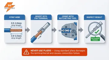
Never use pliers instead of a proper crimping tool. Molex specifications explicitly outline that improper crimps increase contact resistance beyond the 10 mΩ maximum, leading to localized heating that can melt plastic housings under heavy GPU or CPU loads.
Step 4: Test Continuity Before Assembly
Use a multimeter in continuity mode to test each wire before assembly:
- Probe from the crimped pin end to the opposite end — a beep confirms continuity
- Probe adjacent pins next — any beep indicates a short; discard that wire immediately
An undetected short at this stage can drive incorrect voltage into a live component the moment the system powers on. Do this check before inserting pins into housings. Corsair's official PSU testing protocol treats continuity verification as a mandatory pre-power step.
Step 5: Add Sleeving and Insert Pins into Connector Housing
Add sleeving (optional):
- Slide heat shrink tubing over the wire first
- Thread sleeving material onto the wire before final assembly
- Push sleeving to the connector end
- Use a heat gun to shrink the tubing at the connector mouth to secure the sleeve
Insert pins into housing:
- Use the pinout diagram from Step 1 to identify correct pin positions
- Insert each crimped pin into the corresponding slot in the connector housing
- Each pin clicks into place; verify seating with a gentle tug
- Use the pin removal tool to re-seat any incorrectly placed pins
Final verification: Once all pins are seated and sleeving is finished, perform a repeat continuity test on the fully assembled cable. A final visual inspection confirms that all pins are fully seated and no conductor strands are exposed.
Key Variables That Affect Cable Quality and Safety
Even builders who follow the correct steps can end up with unsafe or poor-performing cables if they don't understand and control the key variables that affect the result.
Wire Gauge (AWG)
Wire gauge determines how much current a wire can safely carry before overheating. Using wire that is too thin for a high-current rail (like the 12V EPS or PCIe lines) creates a genuine fire and component damage risk.
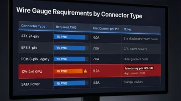
Recommended AWG by connector type:
| Connector Type | Required AWG | Max Current | Notes |
|---|---|---|---|
| ATX 24-pin | 18 AWG | 6-8A per pin | Standard for all 12V, 5V, 3.3V rails |
| EPS 8-pin (CPU) | 18 AWG | 6-8A per pin | Adequate for standard and overclocked loads |
| PCIe 8-pin (legacy) | 18 AWG | 4.5A per pin | 150W total (13.5A across three 12V pins) |
| 12V-2x6 (600W GPU) | 16 AWG | 9.2A per pin | Mandatory per PCI-SIG spec |
| SATA Power | 18 AWG | 1.5A per contact | Standard for 12V, 5V, 3.3V rails |
Undersized wire causes resistance heating, voltage drop, and potentially insulation melt under sustained GPU or CPU load. Investigations by hardware publications have documented that high resistance from poor contact or undersized wiring is a primary cause of melted 12VHPWR/12V-2x6 connectors.
Connector and Pin Compatibility
Connector housings and pins are not universally interchangeable. Pin series (such as Molex Mini-Fit Jr. for ATX connectors) must match both the PSU-side and component-side housings. Using the wrong pin series results in poor contact, arcing, or pins that don't lock properly.
Matching the right terminal to the connector housing matters more than most builders expect:
- ATX and EPS connectors use Molex Mini-Fit Jr. 5556 terminals as the standard
- High-current applications call for Molex Mini-Fit Plus HCS 45750 series terminals, rated up to 11A on 18 AWG wire
- 12V-2x6 connectors require terminals explicitly rated for the higher per-pin current spec
Crimp Quality
A cold or incomplete crimp creates high-resistance contact points that heat up under current load. The impact is intermittent power delivery, voltage fluctuations, or a connector that works initially but fails under load during gaming or rendering.
Molex requires a maximum initial contact resistance of 10 mΩ. Generic pliers cannot achieve the required conductor and insulation barrel geometries that ratcheting crimpers deliver.
Cable Length and Routing
Excessive cable length increases resistance slightly, but more importantly, overly long cables create routing problems that lead to pinched cables, poor airflow, or cables sitting near heat sources inside the case. Keep custom cables as short as the route allows while maintaining enough slack for clean management.
Common Mistakes When Making Custom PSU Cables
Most custom cable failures trace back to the same four mistakes. Avoid these and you eliminate the majority of the risk.
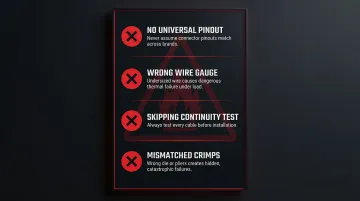
- No universal PSU pinout exists — never assume a pinout matches based on a similar-looking unit or an online "universal" guide. Corsair, EVGA, and Seasonic all use different pinouts even within their own product lines, and that assumption has destroyed high-end components.
- Wrong wire gauge — selecting wire by appearance or grabbing whatever's on hand leads to thermal failures. Undersized wire on a PCIe or EPS connector is particularly dangerous under GPU or CPU load.
- Skipping the continuity test — a two-minute multimeter check before installation can save hundreds of dollars. Builders who skip it often discover shorts or open circuits only after the cable is already seated.
- Mismatched crimps — the wrong die, wrong pin series, or non-ratcheting pliers produces crimps that look fine but fail under current. This failure is often invisible until the system crashes or a connector overheats.
Troubleshooting Common Issues
Even careful builders run into problems. Knowing what to check saves time and prevents the urge to power up a questionable cable and hope for the best. The three issues below cover the most common failure points.
System doesn't power on after installing custom cable
Usually, a pin isn't fully seated in the connector housing, or a wire has an open crimp with no continuity. Start here:
- Re-run continuity test on the fully assembled cable
- Use the pin removal tool to re-seat any suspect pins
- Verify the connector is fully clicked into the motherboard/GPU slot
Connector overheats or smells like burning during use
The most common cause is undersized wire gauge for the current load, or a high-resistance crimp joint on a 12V power rail. Do the following:
- Immediately power off and unplug
- Verify wire AWG against recommended specs for that connector
- Inspect crimps visually and with a multimeter for resistance
- Replace any suspect wires
Cable sleeving bunches or doesn't sit flat
Wires cut to inconsistent lengths are typically the culprit, or heat shrink wasn't applied before the sleeving went on. Fix it with these steps:
- Confirm all wires in the run are the same length
- Redo the heat shrink collar at the connector mouth if sleeving is sliding
- Use cable combs to train the bundle into a flat, parallel run
Frequently Asked Questions
Can you use custom power supply cables with a PSU?
Yes, custom cables can be used with most modular and semi-modular PSUs, but they must be wired specifically to that PSU's pinout. Cables from one brand/model should never be used on a different PSU without verifying full pinout compatibility, as routing incorrect voltages can instantly destroy components.
Are custom power supply cables worth it?
Custom cables make sense for builders who need specific lengths, particular color schemes, or configurations not available in standard kits. That said, they require time, the right tools, and careful safety practices — so weigh that against buying a pre-made kit from a reputable manufacturer.
What wire gauge should I use for custom PSU cables?
Wire gauge depends on the connector type and current load. Use 18 AWG for ATX 24-pin, EPS 8-pin, legacy PCIe 8-pin, and SATA connectors. The PCI-SIG specification mandates 16 AWG for modern 12V-2x6 (600W) GPU power connectors. Never go thinner than the recommended gauge for any high-current application.
Is it safe to make your own PSU cables?
Yes, with proper precautions. Safe DIY cables require:
- Verified pinout for your specific PSU
- Correct wire gauge and matching connector pins
- Continuity and short testing with a multimeter
- No mixing cables between PSU brands without pinout confirmation
Follow manufacturer testing protocols before connecting to live components.
What tools do I absolutely need to make custom PSU cables?
Three tools are required: a ratcheting crimping tool matched to your pin type (such as the ENGINEER PA-09 or PA-20), a precision wire stripper rated for 18–24 AWG, and a digital multimeter for continuity testing. Substituting any of these — using pliers to crimp, for example — produces unreliable connections and real safety risks.
Do I need to buy new connectors and pins, or can I reuse old ones?
Pins should not be reused — crimping permanently deforms them. New pins are inexpensive, and reusing deformed ones risks poor contact and increased resistance. Connector housings can be reused if undamaged and matched to the correct pin series.