Introduction
Undersized pull boxes are one of the more expensive mistakes on a conduit job — and they rarely show up until after the conductors are already pulled. For electrical contractors, construction companies, and OSP contractors, correctly sizing a pull box is both a code requirement under NEC 314.28 and a practical safeguard against conductor damage that doesn't surface until post-installation testing.
Pull box sizing is the process of calculating the minimum required dimensions of a pull box or junction box to ensure conductors can be installed without damaging their insulation.
When pulling large conductors through undersized enclosures, the force required to navigate sharp bends increases sharply, creating sidewall bearing pressure that causes microscopic insulation cracks. These defects often pass initial continuity tests but rapidly deteriorate under sustained load, leading to expensive rework and project delays.
This guide covers the NEC rules that apply, the math behind straight pulls, angle pulls, U pulls, and splices, and the sizing errors that most commonly trigger failed inspections — all for installations with conductors 4 AWG or larger.
Key Takeaways
- NEC 314.28 sizing rules apply to installations with conductors 4 AWG or larger in raceway or cable runs
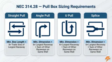
- Straight pulls require a minimum box length of 8 times the largest raceway trade size
- Angle pulls, U pulls, and splices: 6× the largest raceway plus the sum of all remaining raceway sizes on that wall
- Calculate horizontal, vertical, and raceway-to-raceway spacing as three separate calculations
- Always use the largest result from all calculations for each dimension
What Is Pull Box Sizing and When Does It Apply?
A pull box (also called a junction box when splices are present) is an enclosure installed in a conduit or cable run to provide access points that reduce pulling tension and allow direction changes for conductors. For electrical contractors and distributors, understanding when and how these rules apply saves time, materials, and costly rework.
NEC 314.28 governs pull box sizing specifically when insulated conductors of 4 AWG or larger are present. At this threshold, mechanical forces during installation and bend radius requirements become significant enough that standard volume-based calculations no longer provide adequate protection. The insulation on larger conductors is more susceptible to damage from sharp bends and excessive pulling tension.
That's why the code mandates geometry-based sizing rather than simple cubic-inch volume calculations.
This distinction matters because pull box sizing operates on a completely different logic than conduit fill. Conduit fill addresses how many conductors can physically fit inside the raceway based on cross-sectional area. Pull box sizing addresses the box dimensions needed to protect conductor bends and prevent insulation damage during installation — two separate calculations, two separate code sections.
NEC 314.28 Sizing Rules: The Foundation You Need to Know
NEC Article 314.28 is the governing code section that sets minimum dimensions for pull boxes, junction boxes, and conduit bodies containing conductors 4 AWG or larger. The complete code language is available at NFPA.org for reference. These rules translate mechanical principles into enforceable minimums that protect conductor insulation throughout the installation process. The code covers four configurations: straight pulls, angle pulls, U pulls, and splices — each with its own sizing requirement.
Straight Pulls
A straight pull occurs when conductors enter one wall of a box and exit through the directly opposite wall. For straight pulls, the minimum box length must be at least 8 times the trade size of the largest raceway entering that wall.
Key point: Trade size means the nominal conduit designation (such as 2-inch or 3-inch), not the actual internal diameter. Box width only needs to physically accommodate the conduit entries — the code sets no minimum.
Angle Pulls and U Pulls
An angle pull occurs when conductors enter one wall and exit through an adjacent wall. A U pull occurs when conductors enter and exit from the same wall. Both configurations require more space than straight pulls because the conductors must bend inside the box.
For angle and U pulls, the minimum dimension from the raceway entry to the opposite wall equals 6 times the trade size of the largest raceway, plus the sum of the trade sizes of all remaining raceways on the same wall and row.
For example, if a wall has a 3-inch raceway and two 2-inch raceways, the minimum dimension is: (6 × 3) + 2 + 2 = 22 inches.
Splices
When conductors are spliced inside the box, apply the same formula as angle pulls: 6 times the largest raceway trade size plus the sum of remaining raceway trade sizes on that wall and row.
Multiple Rows
When raceways enter in more than one row on the same wall, each row must be calculated individually using the appropriate formula. The largest result from all rows governs the required dimension for that wall. This row-by-row approach prevents undersizing when multiple conduit groups enter at different positions on the same wall.
Quick-Reference Summary
| Pull Type | Minimum Dimension Formula |
|---|---|
| Straight pull | 8 × largest raceway trade size |
| Angle pull | (6 × largest raceway) + sum of remaining raceways on same wall/row |
| U pull | (6 × largest raceway) + sum of remaining raceways on same wall/row |
| Splice | (6 × largest raceway) + sum of remaining raceways on same wall/row |
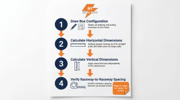
How to Calculate Pull Box Sizing: Step by Step
The four-step approach below ensures accurate calculations every time. The essential starting point is drawing the box layout—skipping this visual step is the single most common source of calculation errors.
Step 1: Draw the Box Configuration
Before performing any calculations, sketch the pull box from a top-down or front view. Mark each wall (left, right, top, bottom), label every raceway entry with its trade size, and trace each conductor's path from entry to exit point.
This visual map reveals whether each conduit run is a straight pull, angle pull, U pull, or splice. Contractors who skip this step often misidentify pull types and apply the wrong formula, resulting in undersized boxes that fail inspection.
Example setup: A box has a 3-inch and a 2-inch raceway on the left wall, with conductors from the 3-inch raceway exiting through a 3-inch raceway on the top wall (angle pull). The 2-inch raceway on the left exits through a 2-inch raceway on the right wall (straight pull).
Step 2: Calculate Horizontal Dimensions
Perform all four horizontal calculations in sequence, then use the largest result:
- Left-to-right straight pull: 8 × largest raceway = 8 × 2 in. = 16 inches
- Right-to-left straight pull: 8 × largest raceway = 8 × 2 in. = 16 inches
- Left-to-right angle pull: (6 × 3 in.) + 2 in. = 18 + 2 = 20 inches
- Right-to-left angle pull: Not applicable in this example
Required horizontal dimension: 20 inches (the largest value from all calculations).
The angle pull governs here. The 6× multiplier applied to a larger raceway will nearly always exceed the straight-pull result — a pattern worth remembering when you have mixed pull types on the same wall.
Step 3: Calculate Vertical Dimensions
The vertical dimension follows the same method — calculate each direction for both pull types and take the largest result. For this example:
- Top-to-bottom angle pull: 6 × 3 in. = 18 inches
- Bottom-to-top: Not applicable in this example
Required vertical dimension: 18 inches.
The vertical calculation is simpler in this case because only one raceway enters from the top. If multiple raceways entered the top or bottom walls, you would calculate each configuration and use the largest result.
Step 4: Verify Distance Between Raceways Containing the Same Conductors
This rule is separate from the dimensional calculations above — and NEC-required. When two raceways in the same box carry the same conductors, the minimum distance between the nearest edges of those raceway openings must be at least 6 times the trade size of the largest raceway.
Measure from the nearest edge of one opening to the nearest edge of the other, excluding locknuts and bushings.
Example: For the two 3-inch raceways carrying the same conductors (left wall entry to top wall exit), the minimum spacing is 6 × 3 in. = 18 inches between the nearest edges of the openings.
Key points to verify before finalizing your layout:
- Spacing is measured edge-to-edge, not center-to-center
- The largest raceway in the pair sets the multiplier, not the average
- This check applies independently of your Step 2 and Step 3 results — a box can pass dimensional checks and still fail here
Key Factors That Affect Pull Box Sizing Calculations
Conduit Trade Size Drives Every Dimension
The trade size of the conduit entering the box is the single most impactful variable in every sizing formula. A one-size increase in trade size can add 6 to 8 inches to the required box dimension, depending on whether the pull is straight or angled.
When sourcing HDPE or PVC conduit through DT Sales Reps, confirm exact trade sizes before sizing any pull box. Assumptions about conduit size lead to undersized boxes and expensive change orders.
Multiple Angle Pulls Grow Box Dimensions Fast
Boxes with multiple angle pulls on the same wall require more room than straight-pull configurations because each additional raceway on that wall adds its full trade size to the sum portion of the formula. The more conductors routing through a single wall at an angle, the faster required dimensions escalate.
NEC 314.28 Does Not Cover Fiber Optic or Signal Cable
NEC 314.28 applies only to electrical power conductors. Fiber optic and signal cables require much larger minimum bend radii than the formula accounts for. According to ANSI/TIA-568.0-E standards, fiber optic cables require:
- 20× the cable outside diameter for installation (dynamic) bends
- 10× the cable outside diameter for long-term static bends
Applying 314.28-based sizing to fiber optic runs produces boxes that are far too small, causing damage during installation, signal attenuation, and potential glass breakage.
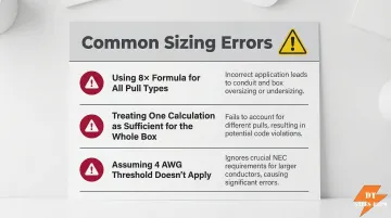
Common Mistakes and Misconceptions in Pull Box Sizing
Three calculation errors account for most pull box compliance failures on the job site. Knowing where contractors go wrong makes it easier to avoid the same pitfalls.
Mistake #1: Defaulting to the 8× straight pull formula for every configuration. Contractors reach for the straight pull formula because it's simpler, but angle and U pulls require a larger dimension — and whichever formula produces the greater result governs. An undersized box forces conductors into sharp bends during the pull, damaging insulation.
That damage often goes undetected until post-installation testing reveals insulation resistance failures, at which point conductor replacement is the only fix.
Mistake #2: Treating one calculation as sufficient for the whole box. Horizontal dimension, vertical dimension, and raceway-to-raceway spacing are three separate calculations — each performed independently, each governed by its own result. A box that meets the horizontal requirement can still fail on vertical depth or spacing, making the entire installation non-compliant.
Mistake #3: Assuming NEC 314.28 doesn't apply because conductors are "small enough." The 4 AWG threshold is absolute. If even one insulated conductor in the box is 4 AWG or larger, the entire box must comply with 314.28 sizing rules.
Ignoring this threshold produces boxes that fail inspection outright — causing project delays and costly rework that a correct calculation would have prevented.
Frequently Asked Questions
What is the depth of a pull box with conduit runs entering at right angles?
For an angle pull, the minimum depth equals 6 times the largest raceway trade size, plus the sum of all remaining raceway trade sizes on that same wall. For example, a 3-inch and a 2-inch raceway on the same wall requires (6 × 3) + 2 = 20 inches minimum.
What is the NEC code for pull box?
NEC Article 314.28 governs pull box and junction box sizing for conductors 4 AWG and larger, specifying minimum dimensions based on raceway trade sizes and conductor routing. The full code text is available at NFPA.org.
How many feet of conduit before a pull box?
NEC 314.28 sets no maximum conduit run length. Pull box placement is driven by pulling tension limits, bend accumulation, and accessibility — most conduit types cap total bends at 360 degrees between pull points per NEC 358/352.
Do pull box sizing rules apply to conductors smaller than 4 AWG?
NEC 314.28 applies only to insulated conductors of 4 AWG or larger. Smaller conductors are governed by box fill requirements under NEC 314.16, which calculates required box volume based on cubic inch capacity rather than linear geometry.
What is the difference between a pull box and a junction box?
A pull box is used primarily to facilitate conductor pulling with no splices, providing access points that reduce pulling tension in long conduit runs. A junction box allows conductor splices, taps, or terminations. Both must be sized per NEC 314.28 when they contain conductors 4 AWG or larger.
Does NEC 314.28 pull box sizing apply to fiber optic or signal cables?
NEC 314.28 is written specifically for electrical power conductors only. Fiber optic cables are governed by NEC Article 770 and require much larger minimum bend radii than the 314.28 formula provides. Applying 314.28 to fiber installations results in boxes that are too small and will damage the cable during installation, causing signal loss.