
Introduction
Fiber optic network deployment is growing at a scale the industry hasn't seen before. The U.S. set an all-time record in 2025 with 11.8 million new Fiber-to-the-Home (FTTH) passings, pushing the national penetration rate above 60%. Behind that number: $42.45 billion in BEAD funding, $20.4 billion in RDOF investments, and 5G densification now covering 51% of the global population.
This volume demands smarter underground cabling infrastructure. Traditional trenching and conduit methods can't keep pace with the need for scalable, cost-effective fiber deployment. Microducts solve that problem — smaller, faster to deploy, and designed to scale without ripping up pavement a second time.
This article covers the definition of a microduct, how it compares to standard ducts, the main types available, installation methods, and key applications driving adoption across FTTH, 5G, and enterprise networks.
TLDR:
- Microducts are 3-16 mm flexible conduits engineered specifically for fiber optic cables
- Cut construction costs by 58% and expand network capacity without new trenching
- Bundled microducts fit inside larger protective conduit, dramatically increasing underground capacity
- Air-blown installation places cable up to 2 km in a single shot, at 100-200 ft/min
- Primary applications include FTTH/FTTP networks, 5G infrastructure, and enterprise fiber deployments
What Is a Microduct? Definition and Key Characteristics
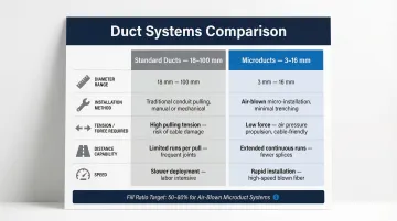
A microduct is a small-diameter, flexible or semi-flexible conduit specifically engineered to house fiber optic cables. Outer diameters typically range from 3 to 16 mm, a stark contrast to standard ducts that measure 25 mm to 100 mm. This size difference enables far greater pathway density within the same trench or outer conduit footprint.
Regulatory Standards and Performance Requirements
Microducts are governed by international standard IEC 60794-5-20, which covers performance requirements for impact resistance, pressure tolerance, and bend radius. In North America, Telcordia GR-3155 defines additional requirements for telecom applications. It ensures microducts can withstand the compression, vibration, and temperature stress required for long-term OSP survival.
Color-coding follows EIA/TIA-598 standards to distinguish individual ducts within bundles, using a 12-color sequence for reliable field identification.
Interior Design and Installation Efficiency
Those compliance requirements carry through to the physical construction. Microduct interiors use low-friction surfaces—sometimes featuring grooves or pre-applied lubricant coatings. Manufacturers like Dura-Line co-extrude ultra-low friction linings (such as SILICORE) that cut the coefficient of friction by up to 60% without wet lubricants. The result: cables can be blown or pulled using less than 50 lbs of force in most configurations.
However, safe pull strength varies strictly by outer diameter:
- 5/3.5 mm duct: 38 lbs maximum
- 12.7/10 mm duct: 227 lbs maximum
Material Construction and Variants
Microducts are made primarily from HDPE (high-density polyethylene) due to its flexibility, resilience, and superior resistance to natural and mechanical damage. Special variants exist for specific environments:
- Indoor use: LSZH (Low Smoke Zero Halogen) materials comply with UL 2024 and NFPA 262 fire safety codes
- Buried outdoor use: Anti-rodent formulations with integrated tracer wires
- Aerial applications: Figure-8 profile with integrated messenger wire
The Bundled Deployment Approach
Microducts are almost always deployed as bundles installed inside a larger protective conduit (such as PVC or HDPE outer duct), rather than as standalone conduit. This bundled approach is what drives their scalability: up to seven 12.7/10 mm microducts fit inside a standard 2-inch conduit, multiplying trench density without expanding the footprint.
Microducts vs. Standard Ducts: Key Differences
Diameter and Density Advantages
The primary distinction is diameter. Standard HDPE sub-ducts run 18-63 mm (with 40-50 mm being common), while microducts are 3-16 mm. This size reduction enables far greater duct density within the same trench or outer conduit footprint, allowing network operators to install more independent pathways in a single civil construction project.
To ensure successful air-blown installation, the relationship between cable outer diameter and microduct inner diameter is critical. Engineering guidelines recommend a target fill ratio between 50% and 80%. Fill ratios exceeding 80% restrict the airflow required to "float" the cable, severely decreasing blowing distances.
Installation Method Differences
| Aspect | Standard Ducts | Microducts |
|---|---|---|
| Installation Method | Pulling with higher tension limits | Optimized for air-blown/jetting |
| Typical Tension | Varies by cable type, often 200+ lbs | Less than 50 lbs for most configurations |
| Distance Capability | Limited by cable weight and friction | Up to 2 km single-shot with air-blowing |
| Speed | Manual or mechanical pulling | 100-200 ft/min (up to 490 ft/min possible) |
Pulling is still possible in microducts but is generally limited to shorter distances (300-400 m for thick-walled variants, depending on route undulation).
Branching Without Splicing
In traditional duct networks, branching fiber optic cables requires fusion splicing—a complex, costly process. At typical labor rates, a single fusion splice in a drop location costs $30 to $60 in labor alone, not including equipment setup time.
With microducts, a window cut in the outer protective duct lets technicians tap and re-route individual microducts using simple push/pull connectors—no splicing required. Fiber can be jetted end-to-end without intermediate splices, eliminating attenuation losses and cutting skilled labor requirements significantly.
Cost and Capacity Trade-offs
Standard ducts are simpler per-unit but offer less flexibility and density. Microducts require more upfront planning—the payoff comes in long-term cost and capacity gains:
- 58% reduction in Total Cost of Ownership (TCO) compared to traditional cables in standard conduit
- Lower long-term construction costs by deferring civil work until capacity is actually needed
- Increased underground capacity without additional trenching
- On-demand network growth that scales with actual subscriber uptake
Types of Microducts
Microducts are available in two primary wall construction categories—thick-walled and thin-walled—and the choice between them dictates whether the microduct can be directly buried or must be installed inside a larger outer duct.
Thick-Walled Microducts
Thick-walled microducts (designated "DB" for Direct Burial) are designed for direct burial or use inside larger outer conduit. They're available in three configurations:
- Tight bundles enclose multiple microducts in a thin outer sheath, delivering the highest pathway density for standard cable installation.
- Loose bundles allow freedom of movement within the sheath, reducing pull friction for short runs of 300-400 m into existing ducts.
- Flat bundles lay microducts laterally with no overlap, making them the go-to profile for narrow microtrenching and slot-cut applications. They can be directly buried or pulled into larger ducts.
Thin-Walled (Protective) Microducts
Thin-walled microducts (designated "DI" for Direct Install) lack the structural protection needed for direct burial and must be installed within larger outer ducts or inside buildings. They share the same tight, loose, and flat bundle configurations as thick-walled types but are more flexible and suited for indoor environments where space is tight. The flat LSZH variant is the standard choice for building riser and plenum applications, meeting UL 2024 and NFPA 262 fire safety requirements.
Aerial Microducts
Aerial microducts are a specialized variant used for last-mile connections to subscribers. Key characteristics include:
- Built in a figure-eight (Fig. 8) profile with an integrated support messenger
- Used for above-ground deployment where trenching is impractical or cost-prohibitive
- Available with Extra High-Strength (EHS) galvanized steel or dielectric messenger wire
- Support spans of 60-100 meters — longer than the commonly cited sub-50 meter limit
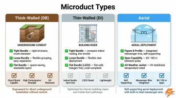
Dura-Line's Figure-8 aerial microducts use a 1/4" steel strand rated for 6,650 lbs safe working pull strength, making them a reliable choice for demanding span installations.
How Microducts Are Installed
Cable Placement Methods
GR-3155 and industry practice define three accepted cable placement methods:
1. Pre-installed Cable is extruded directly into the microduct during manufacturing, eliminating field installation. This approach allows operators to deploy the duct and fiber in a single dig, bypassing the need for blowing equipment entirely.
2. Cable Pulling A pull line is used to draw fiber cable through the duct manually or mechanically. Practical for shorter or straighter runs, typically limited to 300-400 m for thick-walled variants. Specialized cables can be pushed up to 300 m, though 80-100 m is more typical for standard drop cables.
3. Air-Blown/Jetting The preferred method for microducts, using high-volume compressed air to propel cable through the duct. Key specifications:
- Air pressure: Up to 16 bar (230 psi) for optimal cable floating (not the commonly cited 20-25 psi)
- Speed: 100-200 ft/min typical (up to 490 ft/min possible)
- Distance: Up to 2 km (6,500 ft) in a single shot
- Mechanism: Tractor mechanism pushes the cable while compressed air creates viscous drag, floating the cable through the duct and minimizing sidewall friction
Underground Installation Techniques
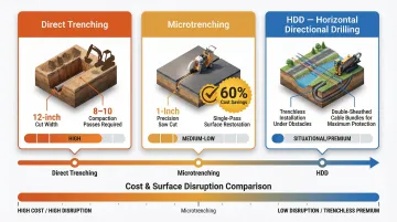
Direct Trenching Traditional open-cut method with the highest surface impact:
- Minimum 12-inch wide cut required
- Heavy steel plating needed for active traffic lanes
- Requires 8-10 passes of backfill and compaction to restore
Microtrenching A widely adopted technique that cuts surface disruption to a fraction of traditional methods:
- Single saw cut (1 inch or less wide)
- Allows immediate vehicle traffic crossing
- Restored in a single pass using hot polymer or grout
- Eliminates 8-10 backfill passes required by traditional trenching
- Yields approximately 60% cost savings over traditional trenching
Horizontal Directional Drilling (HDD) Used for trenchless installation under roads, rivers, or other obstacles. Manufacturers produce double-sheathed microduct bundles specifically designed to withstand the high tensile pullback loads and external pressures of HDD installations.
Each of these methods supports phased network deployment — microducts can coexist in the same handhole or conduit system with standard ducts, so upgrades don't require tearing out existing infrastructure.
Critical Accessories
Completing a microduct installation requires GR-3155 compliant accessories:
- Straight Couplers: Join duct runs; must withstand up to 150 psi (10 bar) of blowing pressure without leaking or separating
- End Caps: Critical for blocking water and gas ingress at terminal points, manholes, and buildings during construction
- Reducers: Enable transitions between different microduct sizes
- Branching Boxes: Protective closures for exposed ducts and connectors at mid-span window cuts in direct-buried installations
Common Applications of Microducts
Fiber to the Home (FTTH) and Fiber to the Premises (FTTP)
This is the primary use case driving microduct adoption. Microducts enable cost-effective, scalable last-mile fiber deployment by allowing individual duct paths to be created on demand without trenching new routes each time a subscriber is added.
In the UK, Openreach trialed micro-ducting to connect properties with direct buried copper feeds. By using a twin-saw microtrenching method, they installed armored microducts and pushed 8x4 mm fiber cables 80-100 m directly to the premises, avoiding the cost of blowing equipment for the final drop.
5G Small Cell and Backhaul Infrastructure
5G densification requires fiber to reach thousands of new small cell antennas. Dense, space-efficient duct routing is critical in urban environments where right-of-way is limited. Microducts allow operators to lower their pole attachment profile and incrementally blow fiber to new nodes as the wireless network expands.
Enterprise and Campus Fiber Networks
"Combined Ducts" (hybrid bundles) are used in enterprise environments. For example, a single bundle containing a 14/10 mm duct for a 288-fiber metro backbone alongside 8/4 mm ducts for local distribution allows a campus to build its entire network hierarchy in a single pull.
Data Center Interconnects
High-density fiber pathways between data centers benefit from microduct's ability to maximize conduit capacity while maintaining flexibility for future upgrades.
Municipal Broadband Buildouts
In Bandung, Indonesia, the municipality halted sprawling open-cut fiber construction due to traffic gridlock. The solution was a mandated open-access network using microtrenching and bundled microducts, forcing operators to share pathways and access spare tubes without additional excavation.
Across all these deployments, the ability to pre-install empty microducts and activate them later — without new construction — is what makes the approach practical. DT Sales Reps supplies HDPE conduit and microduct-compatible materials to distributors and OSP contractors specifying this infrastructure.
Advantages of Microducts Over Traditional Cabling
Operational Advantages
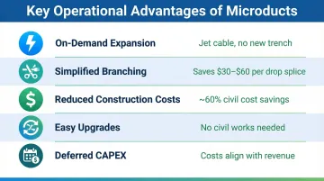
Microducts deliver several key operational benefits:
- On-demand network expansion: Add a subscriber by jetting a new cable rather than digging a new trench
- Simplified branching: Window-cut mid-span branching eliminates $30–$60 in per-drop fusion splicing labor
- Reduced construction costs: Fit more capacity into smaller trenches; microtrenching reduces civil costs by approximately 60%
- Easier upgrades: Replace or upgrade cables in the future without new civil works
- Deferred CAPEX: Only purchase and blow fiber when a subscriber requests service, perfectly aligning material costs with incoming revenue
Scalability and Future-Proofing
Empty microducts act as pre-built pathways. Contractors and network owners can install duct bundles today and fill them as demand grows, reducing stranded investment and enabling a phased build approach aligned with actual subscriber uptake.
That phased approach also translates directly to cost savings: installing a 4-way 16/12 mm microduct bundle and blowing a 288-fiber micro cable costs 58% less than installing four 1.25" standard conduits with traditional cables — a TCO reduction that makes microducts a practical default for network operators planning ahead.
Environmental Benefits
Micro cabling systems offer measurable environmental advantages. A traditional fiber cable is 2 to 2.5 times larger in diameter than a micro cable, resulting in a volume and weight difference of 4 to 6 times. Less plastic in manufacturing means more cable per truckload. Together, these factors produce a 300% to 1445% reduction in CO2 emissions during logistics and installation compared to legacy conduit builds.
Frequently Asked Questions
What is a microduct?
A microduct is a small-diameter (3–16 mm OD) flexible conduit used to house fiber optic cables, typically installed in bundles inside a larger protective outer duct. Microducts feature low-friction interiors optimized for air-blown cable installation.
What is the difference between a duct and a microduct?
Standard ducts range from 18–100 mm in diameter and can house cables directly. Microducts (3–16 mm) are much smaller, bundled inside larger ducts, and optimized for air-blown installation and on-demand network branching without splicing.
Why are microduct cables popular?
Microducts offer several advantages over traditional conduit systems:
- Cut construction costs by approximately 60%
- Enable network growth without new trenching
- Simplify branching without splicing
- Support air-blown installation up to 2 km in a single shot
What size is a microduct conduit?
Microducts have outer diameters ranging from 3 to 16 mm, with common sizes determined by the fiber cable they house. For example, up to 144 fibers can be installed in an 8 mm inner diameter microduct using a 6.4 mm OD cable.
Can microducts be used for aerial installation?
Yes, specialized aerial microducts exist in a figure-eight profile with an integrated messenger wire. These support spans of 60–100 meters (not the commonly cited <50 meter limit) and are typically used for above-ground subscriber connections where trenching is impractical.
What materials are microducts made from?
Microducts are primarily made from HDPE (high-density polyethylene). Special variants include LSZH (Low Smoke Zero Halogen) for indoor/plenum use and anti-rodent formulations for buried outdoor applications. All variants are color-coded per EIA/TIA-598 standards for easy identification.