Introduction
Parallel offset bending occurs when two or more conduits run side by side and all require matching offset bends to navigate an obstacle while maintaining equal spacing throughout the entire run. Most electricians know the basic offset technique — parallel offsets add one more calculation that determines whether the finished run looks clean or gets called back.
Skip the progression adjustment and the gaps between conduits compress through the offset section, producing a visible defect that fails industry workmanship standards. NECA 101-2020 requires steel conduit installations to meet "neat and workmanlike" alignment requirements.
The code risk goes beyond appearance. Improper spacing can trigger NEC 310.15(C)(1) ampacity derating requirements when raceways are bundled without adequate separation for more than 24 inches.
This guide walks through the progression formula, step-by-step execution, and troubleshooting strategies to deliver clean, code-compliant parallel offset bends.
Key Takeaways
- Calculate progression distance using tan(½ × bend angle) × center-to-center spacing for consistent spacing through the offset
- Use the same bend angle consistently across all conduits in the group
- Advance bend marks on each successive conduit by the progression distance
- Verify spacing before, during, and after the offset section before mounting
- Rotate each conduit exactly 180° between bends and confirm all marks before each bend
How to Bend Parallel Offsets in Conduit
Step 1: Measure the Obstacle and Plan Your Offset
Measure the height of the obstacle or elevation change the conduits must clear. This determines the required offset depth for all conduits in the group. Choose your bend angle—common choices are 30°, 45°, or 60°—and use it consistently across all conduits. The progression formula only works when every conduit uses the same angle.
Measure and confirm the center-to-center (C-C) spacing between the conduits. This is your key input for the progression formula. Use a tape measure to verify the actual installed spacing, not nominal spacing, as even small variations will affect your calculations.
Key planning considerations:
- All conduits must clear the same obstacle height
- Bend angle choice affects both offset distance and progression distance
- C-C spacing must be measured accurately and maintained throughout
Step 2: Calculate the Progression Distance
Apply the parallel offset progression formula:
Progression Distance = tan(½ × bend angle) × C-C spacing
For example, if you're using 45° bends with 2" C-C spacing:
- Half the bend angle = 22.5°
- tan(22.5°) ≈ 0.414
- Progression distance = 0.414 × 2" ≈ 0.83"
This progression distance is the amount you shift the bend marks forward on each successive conduit. The first conduit gets no shift. The second conduit gets one progression distance added (0.83"). The third gets two progression distances added (1.66"), continuing by one increment per conduit.
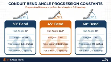
Common progression constants by angle:
| Bend Angle | Half Angle | Tangent Value | Example (2" C-C) |
|---|---|---|---|
| 30° | 15° | 0.2679 | 0.54" progression |
| 45° | 22.5° | 0.4142 | 0.83" progression |
| 60° | 30° | 0.5774 | 1.15" progression |
Separately, calculate the distance between the two bends on each conduit using the standard offset multiplier:
- 30° bends: multiply offset depth by 2.0
- 45° bends: multiply offset depth by 1.414
- 60° bends: multiply offset depth by 1.2
This distance-between-bends figure applies equally to all conduits in the group.
Step 3: Mark and Bend the First Conduit
Mark the first conduit at the standard offset positions using your distance-between-bends calculation from Step 2. The first conduit establishes the baseline—its marks receive no progression shift.
Bending sequence:
- Set the conduit in the bender and align the first mark with the bender arrow
- Bend to the selected angle (verify on the bender's degree scale)
- Rotate the conduit exactly 180°
- Align the second mark with the bender arrow
- Complete the second bend at the same angle
Verify the offset depth and angle on the finished first conduit using a level and tape measure before proceeding. Any error on the first conduit will propagate through the entire group. Once confirmed, this conduit becomes your template for advancing marks on every conduit that follows.
Step 4: Advance Marks and Bend Each Subsequent Conduit
For each additional conduit, add the calculated progression distance cumulatively:
- 2nd conduit: add 1× progression distance to both marks
- 3rd conduit: add 2× progression distance to both marks
- 4th conduit: add 3× progression distance to both marks
The distance between the two bends on each conduit stays the same—only the starting position shifts forward.
Bend each subsequent conduit using identical technique and angle as the first. The angle does not change; only the longitudinal position of the offset shifts along the conduit length.
Final verification:
Lay all bent conduits side by side on a flat surface. Measure C-C spacing at three points:
- Before the offset section
- Through the offset bends
- After the offset section
If spacing narrows through the bends, you didn't apply the progression distance correctly. Fix it on the ground now — re-bending after mounting costs far more time.
When Should You Use Parallel Offset Bending?
Use parallel offset bending whenever multiple circuits in parallel raceways must clear the same beam, pipe, cable tray, or structural obstacle. This is common in commercial electrical installations, industrial panel feeds, and OSP conduit runs where maintaining uniform conductor spacing is required by NEC 300.3(B).
Typical scenarios:
- Multiple conduit runs navigating around HVAC ductwork in commercial buildings
- Parallel feeds to industrial panels clearing structural steel or piping
- OSP telecommunications conduit groups routing around underground obstacles
- Any installation where visible conduit alignment will be inspected or is customer-facing
That said, not every multi-conduit job needs the full parallel offset treatment.
When to skip the calculation:
If only one or two conduits are involved and appearance is not a priority, individual offsets will work. On any professional or inspection-ready installation, though, parallel bending is expected — and NEC 310.15(C)(1) ampacity derating means consistent spacing is a code requirement with real consequences for conductor ratings, not just a cosmetic preference.
What You Need Before You Start
Tools required:
- Hand bender correctly sized to match conduit diameter (mismatched benders cause flattening and structural damage)
- Tape measure (25' minimum)
- Permanent marker or soapstone pencil
- Level or digital angle finder
- Calculator or reference table for tangent values
Materials needed:
- Conduit of uniform type and diameter for all parallel runs
- Confirm consistent outside diameter (OD) across the batch — OD variations throw off center-to-center measurements and progression calculations
DT Sales Reps carries HDPE conduit, PVC conduit, and microduct in uniform sizing, which matters when you're running parallel offsets where OD consistency is critical.
Knowledge prerequisites:
You must already be competent at basic offset bending before attempting parallel offsets:
- Calculating distance between bends using multipliers
- Maintaining the 180° flip between bends
- Reading bender degree marks accurately
- Recognizing and preventing dog legs
Parallel offsets build on these fundamentals. They add one calculation layer, but everything you already know about single offsets still applies.
Key Parameters That Affect Results
Parallel offset quality depends on controlling a small set of variables. An error in any one of them cascades visibly across every conduit in the group as misalignment.
Bend Angle
The angle controls both the distance-between-bends multiplier and the tangent value in the progression formula — small deviations have an outsized effect on both. One conduit bent at 44° instead of 45° produces a different offset depth, which breaks parallel alignment across the group.
Two practices prevent this:
- Verify the angle on the bender's degree scale for every individual bend
- Account for springback — conduit straightens slightly after pressure releases, so slightly over-bend to hit your target resting angle
Center-to-Center (C-C) Spacing
C-C spacing is the direct multiplier in the progression formula. If the planned spacing doesn't match the actual installed spacing on the wall or tray, the progression distance will be off. Too little C-C creates crowded groups with no clearance for connectors; too much wastes space. Always measure actual installed spacing — not nominal spacing — before calculating.
Number of Conduits in the Group
Each additional conduit adds one more progression distance increment. On large groups, this cumulative longitudinal shift is significant — ignore it when pre-cutting lengths and the last conduits in the group will fall short of their termination point. Add appropriate length allowance before cutting.
Marking Accuracy
Calculations are only as accurate as the marks transferred to the conduit. An error of 1/8" at the marking stage produces visible misalignment in the finished run. Before bending each piece:
- Use a square to wrap marks cleanly around the conduit for the second bend reference
- Verify each conduit's marks against the calculated values — checking after the bend is too late
Common Mistakes When Bending Parallel Offsets
Most parallel offset problems trace back to a handful of repeatable errors. Knowing what to watch for saves time on corrections later.
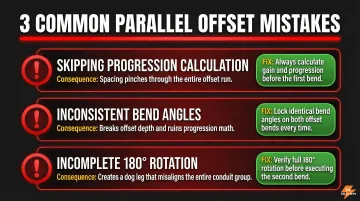
- Skipping the progression calculation: Copying the same bend marks onto every conduit causes spacing to visibly pinch through the offset. The gaps through the offset will be narrower than the straight portions, creating an unprofessional appearance and potential code issues.
- Using inconsistent bend angles: Bending the first conduit at 45° and a later one at 30° — even from a slipped bender — breaks both the offset depth and the progression math simultaneously, making correction difficult.
- Failing to rotate the conduit a full 180° before the second bend: This creates a "dog leg" — bends that are skewed and out of plane. On a parallel run, a dog leg on one conduit throws off the entire group.
Troubleshooting Issues While Bending Parallel Offsets
Most problems with parallel offsets fall into three categories: narrowing spacing, out-of-plane bends, or inconsistent offset depth. Catching these early — before mounting — saves a full re-run.
Spacing Narrows Through the Offset
The progression distance was not applied — or the same marks were used on all conduits instead of staggering them. Re-calculate the progression distance with the correct formula and verify each conduit's marks before bending. If the conduits are already bent, check whether they can be re-bent or need to be replaced.
Dog Leg (Bends Are Out of Plane)
The conduit was not rotated exactly 180° before the second bend, or the bender drifted out of plane during bending. To correct this on the next run:
- Use a flat floor or table as a reference surface for the second bend
- Lay the conduit flat after the first bend and confirm it isn't twisted before continuing
Offset Depths Are Inconsistent Across Conduits
Inconsistent pressure or travel between conduits produces different actual angles, even when the same bender markings are used. Use a bender with a clear degree scale and verify each bend with a digital angle finder or level before moving on. Make a test bend on scrap conduit to confirm the angle before starting the production run.
Conclusion
Bending parallel offsets correctly comes down to one non-negotiable step: advancing each successive conduit's marks by the progression distance (tan of half the bend angle × C-C spacing). Equal bend angles without that offset produce misaligned runs every time.
The most common failures come from skipping the progression formula or applying bend angles inconsistently. Both are avoidable — calculate your marks, verify spacing against the layout, and confirm everything before the first bend is made.
Consistent materials matter just as much as consistent technique. DT Sales Reps supplies HDPE conduit, PVC conduit, and microduct to electrical contractors and distributors who need the right stock on hand when the job calls for it. Reach them at 281-900-1506 or DavidS@DTTexas.com.
Frequently Asked Questions
How can an electrician ensure offsets remain aligned when installing multiple parallel conduits?
Apply the parallel offset progression formula: add tan(½ × bend angle) × C-C spacing to the bend marks of each successive conduit. After bending, lay all conduits side by side and measure C-C spacing at multiple points to verify equal spacing before mounting.
What is the formula for calculating the progression distance in parallel conduit offsets?
The formula is tan(½ × bend angle) × center-to-center spacing. With 45° bends and 2" C-C spacing, for example: tan(22.5°) ≈ 0.414, so 0.414 × 2" ≈ 0.83" progression distance per conduit.
Does the bend angle affect how much progression distance is needed?
Yes. Steeper angles require greater progression distances because the tangent value of half the angle increases with angle size. For the same C-C spacing, 45° bends require more progression offset than 30° bends (0.414 vs. 0.268 tangent multiplier).
Can parallel offset bending be done when the conduits in the group are different sizes?
Different conduit sizes have different outside diameters, which changes the actual C-C distance between their centerlines. Each conduit pair requires its own C-C measurement, making the progression calculation more complex and requiring careful marking for each conduit.
What is the difference between parallel offsets and concentric bends?
Parallel offsets navigate an obstacle by shifting all conduits in the same direction while maintaining their side-by-side spacing. Concentric bends involve conduits that follow sweeping arcs at increasing radii (like 90° elbows), each with a different developed length.
How do I know if my parallel offset came out correctly before I mount the conduits?
Lay all bent conduits side by side on a flat surface and measure C-C spacing at multiple points—before, during, and after the offset section. The spacing should remain equal throughout. If spacing narrows through the bends, the progression distance wasn't applied correctly.