Introduction
Junction boxes are code-required enclosures for wire splices and circuit branches — and when they're installed wrong, the consequences show up in fire reports. According to the NFPA, arcing is the heat source in 63% of home fires caused by electrical failure — and loose connections inside junction boxes are a primary driver.
This guide covers box selection, NEC-compliant installation, proper wire connections, and troubleshooting the failures that show up after the job is done.
TLDR:
- Every wire splice requires an NEC-approved junction box — no exceptions
- Size boxes using NEC 314.16(B) fill calculations based on conductor gauge and count
- Keep junction boxes permanently accessible — burying them behind drywall is a code violation
- Torque all splices to manufacturer specs — loose connections are the top cause of arc faults
- Outdoor installations require NEMA-rated enclosures (3R minimum, 4X for corrosive environments)
What Is a Junction Box and When Do You Need One
A junction box is an enclosed housing — metal, plastic, or fiberglass — designed to protect electrical wire connections from physical damage, moisture, and fire risk.
NEC Article 300.15 requires that all wire splices be made inside an approved enclosure. The reason is straightforward: exposed splices are a leading fire cause, and NFPA data shows local fire departments respond to an estimated 46,700 home electrical fires annually.
Common scenarios requiring a junction box:
- Branching a circuit in two or more directions
- Extending an existing circuit run
- Protecting splices in conduit systems where wires transition between runs
- Connecting multiple cables at a single point in commercial installations
Junction Box vs. Related Enclosures
On the job, these terms get used interchangeably — but the distinctions matter when specifying materials:
- Junction box: general-purpose enclosure for wire splices and branch connections
- Outlet box: houses receptacles or switches; may also serve as a junction point
- Fixture box: specifically rated to support lighting fixtures
- Splice box: informal term often used interchangeably with junction box; technically refers to enclosures protecting single wire splices. Note that the NEC does not define "splice box" as a separate regulatory category — Article 314 governs all boxes used as outlet, device, junction, or pull boxes.
Choosing the Right Junction Box: Materials, Size, and Type
Metal vs. Plastic Junction Boxes
Metal boxes offer superior strength, fire resistance, and grounding continuity. Use metal when:
- Installing with metallic conduit (EMT, rigid, IMC)
- Working in commercial or industrial environments
- Fire resistance is critical
- Physical impact is likely
Plastic (PVC) boxes are lighter and lower-cost but have limitations:
- Restricted to non-metallic cable (Romex) installations
- Cannot provide grounding path through the box itself
- Subject to strict flush-mounting rules per NEC 314.20
- Must be flush with combustible surfaces or project from them; in noncombustible materials, cannot be recessed more than 1/4 inch
Box Sizing: NEC Fill Calculation Rules
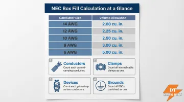
Overcrowded boxes are a leading code violation. NEC 314.16(B) requires specific volume allowances per conductor:
| Conductor Size (AWG) | Free Space Required Per Conductor |
|---|---|
| 14 AWG | 2.00 cubic inches |
| 12 AWG | 2.25 cubic inches |
| 10 AWG | 2.50 cubic inches |
| 8 AWG | 3.00 cubic inches |
| 6 AWG | 5.00 cubic inches |
Counting rules:
- Each conductor originating outside the box and terminating inside counts as one allowance
- Internal cable clamps count as one allowance (based on largest conductor)
- Each device (switch, receptacle) counts as two allowances (based on largest wire)
- Up to four equipment grounding conductors count as one allowance
- Each additional ground beyond four adds one allowance for every four conductors
Standard 4-inch square box capacities:
- 1-1/4" deep: 18.0 cubic inches
- 1-1/2" deep: 21.0 cubic inches
- 2-1/8" deep: 30.3 cubic inches
The 2-1/8" deep box is most common for commercial branch circuits, reducing the risk of fill violations while accommodating bulky smart devices.
Cover Plate Requirements
All junction boxes must have properly secured covers rated for the installation environment. NEC 314.29 explicitly requires that boxes remain accessible without removing building finishes.
Never bury junction boxes behind drywall. This is one of the most frequently cited code violations during inspections.
Cover types:
- Standard blank covers for indoor, dry locations
- Weatherproof covers with gaskets for outdoor/wet locations
- NEMA-rated covers for harsh environments (see NEC compliance section)
Tools and Materials Checklist
Essential tools:
- Non-contact voltage tester or voltmeter
- Wire strippers rated for the AWG being used
- Screwdrivers (flathead and Phillips)
- Cable clamps (for metal boxes)
- Wire connectors (wire nuts, push-in, or weatherproof types)
- Mounting hardware (screws, brackets)
Quality materials matter. From conduit and cable entering the box to the connectors used inside, every component affects long-term reliability. Cutting corners on materials is one of the most common causes of failures that show up months after installation.
Electrical contractors sourcing conduit, cable, and jobsite essentials in volume can work with DT Sales Reps to keep projects stocked and on schedule. Their product range covers HDPE conduit, PVC conduit and pipe, pull boxes, heavy-duty cable, and safety equipment including helmets, gloves, and jobsite signs.
How to Install and Wire a Junction Box: Step-by-Step
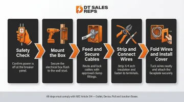
Step 1: Safety First
Turn off the circuit breaker controlling the circuit. Use a non-contact voltage tester to confirm all wires in the work area are fully de-energized before touching anything. Never rely on a breaker label alone—verify with a tester at the work location.
Step 2: Mount the Box
Secure the junction box flush to a structural member (stud or joist) using screws or appropriate mounting hardware. For metal boxes, knock out the appropriate entry holes and thread in cable clamps. Plastic boxes typically have integral spring clamps built in. The box face must be flush with the finished wall surface (combustible materials) or recessed no more than 1/4 inch (noncombustible materials).
Step 3: Feed and Secure Cables
Route cables or conduit into the box through the clamps. The cable sheath (outer jacket) should extend 1/4 to 1/2 inch past the clamp into the box. Each individual conductor should extend approximately 6 inches inside for working room. Tighten clamp screws firmly without crushing the cable jacket—over-tightening damages insulation and creates future failure points.
Step 4: Strip Conductors and Make Connections
Strip 3/4 inch of insulation from each conductor. Make connections in this order:
- Ground wires first: Connect bare copper or green ground wires together. If using a metal box, add a pigtail to the ground screw per NEC 250.148(C)
- Neutral wires second: Connect white neutral wires together
- Hot wires last: Connect black (and red if present) hot wires
Use wire connectors rated for the AWG and number of conductors being joined. Tug each connection firmly to confirm it is secure—loose connections cause 63% of electrical fires. Follow manufacturer torque specifications when available.
Step 5: Fold Wires and Install Cover
Carefully fold connected wire groups back into the box without forcing or over-bending them. Install the appropriate cover plate and secure with screws. Restore power and verify circuit function with a voltage tester or by testing connected loads.
Conduit Entry Considerations
If your installation uses conduit rather than cable, the rules at the box entry change. When cables enter a junction box through electrical conduit (rigid, EMT, or HDPE), the conduit must be secured with approved fittings and connectors at the box entry—not left loose. NEC 314.17 requires that conductors be protected from abrasion; metal boxes used with unprotected conductors must have insulating bushings at conduit ends.
Conduit support intervals:
- EMT, rigid, and IMC: Within 3 feet of the box, then every 10 feet
- PVC (1/2" to 1"): Within 3 feet of the box, then every 3 feet
DT Sales Reps supplies HDPE conduit and pull boxes for electrical contractors and distributors working on outdoor and telecommunications infrastructure projects.
How to Troubleshoot Common Junction Box Wiring Problems
These problems account for most junction box failures in the field. Work through each systematically with power off before inspecting connections.
Problem: Circuit Breaker Trips Repeatedly
Cause: Overloaded junction box where too many high-draw circuits share a single branch, or a wire-to-wire short caused by a loose connector inside the box.
Solution: Open the box with power off. Inspect all connections for loose or touching bare conductors. Verify box fill capacity has not been exceeded using NEC 314.16(B) calculations. If conductors are crammed too tightly, upgrade to a larger enclosure.
Problem: Intermittent Power Loss or Flickering
Cause: High-resistance loose connection at a wire nut or push-in connector inside the box.
Solution: Shut off the circuit. Remove each connector and inspect conductor ends for corrosion or strand damage. Re-strip if necessary, removing 3/4 inch of insulation. Remake each connection securely, following torque specifications. Test connections by tugging firmly—if any wire pulls free, the connection is inadequate.
Problem: Junction Box Feels Warm or Hot to Touch
Cause: One or more of the following: undersized wiring for the circuit's current draw, a failing connection generating resistance, or conductors crammed too tightly in an undersized box.
Solution: Confirm wire gauge matches circuit amperage (14 AWG = 15A max, 12 AWG = 20A max, 10 AWG = 30A max). Check for damaged insulation or scorching inside the box. Upgrade to a larger enclosure if fill limits are exceeded. Replace any connections showing heat damage.
Problem: Moisture or Condensation Inside the Box
Cause: Improperly sealed conduit entries or use of indoor-rated boxes in outdoor or wet locations. IEEE data indicates up to 40% of outdoor electrical breakdowns link to moisture ingress.
Solution: Use weatherproof boxes with gasketed covers in damp/wet locations. Seal conduit entry points with appropriate fittings. NEC 314.15 permits approved weep holes (1/8" to 1/4") to prevent internal condensation. Replace any corroded connectors or damaged wire ends before resealing.
Problem: Visible Burn Marks or Melted Insulation
Cause: Arc fault or sustained overcurrent condition.
Solution: This is a serious safety hazard. De-energize the circuit immediately. Replace all affected wiring, connectors, and the box itself before restoring power. Document the damage and consult an electrician or Authority Having Jurisdiction (AHJ) if the root cause is unclear. Burn damage can indicate an arc fault condition requiring AFCI protection evaluation per NEC 210.12.
NEC Rules and Code Compliance Every Electrician Should Know
Key NEC Requirements
- NEC 300.15 — Enclose all splices in approved enclosures; exposed wire connections violate code and create fire hazards.
- NEC 314.29 — Keep boxes accessible at all times; concealing them behind permanent finishes is prohibited and the wiring must be reachable without damaging the building structure.
- NEC 314.16 — Stay within box fill limits; calculate cubic-inch allowances per conductor gauge and count all conductors, devices, clamps, and grounds.
Outdoor, Wet-Location, and Underground Requirements
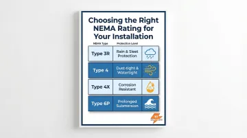
Standard indoor boxes used outdoors are one of the most common code violations. Outdoor and wet-location installations require NEMA-rated enclosures:
| NEMA Type | Protection Level |
|---|---|
| Type 3R | Outdoor use; protects against rain, sleet, snow; undamaged by ice formation |
| Type 4 | Indoor/outdoor; protects against windblown dust, rain, splashing water, hose-directed water |
| Type 4X | All Type 4 protections plus corrosion resistance for harsh environments |
| Type 6P | Indoor/outdoor; protects against hose-directed water and prolonged submersion; corrosion resistant |
Underground installations are considered wet locations. Conductors inside underground raceways and junction boxes must be rated for wet locations (e.g., THWN).
Licensing and Permit Requirements
Before starting any junction box work, confirm these compliance basics:
- Homeowners can legally install junction boxes for basic residential work in many jurisdictions, but commercial and industrial work typically requires a licensed electrician.
- OSHA 1910.333 restricts energized electrical work to "qualified persons" with demonstrated skills and safety training.
- There is no federal electrician license — states and local jurisdictions govern licensing independently.
- Verify permit and inspection requirements with your local Authority Having Jurisdiction (AHJ) before starting work.
Frequently Asked Questions
Do you need an electrician to install a junction box?
Homeowners can install junction boxes for basic residential work in most jurisdictions, but commercial, industrial, and high-voltage applications generally require a licensed electrician. Always check permit requirements with your local AHJ first, as regulations vary widely by state and municipality.
What are the rules for junction boxes?
All wire splices must be housed in an approved enclosure per NEC 300.15. The box must not exceed its fill capacity per NEC 314.16(B). The cover must always be installed, and the box must remain permanently accessible without removing building finishes per NEC 314.29.
What is the difference between a junction box and a splice box?
The terms are often used interchangeably — "splice box" typically refers to an enclosure protecting a single wire splice, while "junction box" is a broader term for any approved enclosure housing one or more connections, including branch points. The NEC does not define them as separate regulatory categories.
Can a junction box be hidden behind drywall?
No. Concealing a junction box behind a permanent wall surface violates NEC 314.29 requirements. The box must remain accessible for inspection and maintenance without damaging building finishes.
What size junction box do I need?
Box size is determined by NEC 314.16(B) fill calculations based on conductor count and gauge. The standard 4-inch square box (2-1/8" deep, 30.3 cu in) handles most residential branch circuits — allow 2.25 cu in per 12 AWG conductor and 2.0 cu in per 14 AWG conductor for higher wire-count applications.